Bug #1521
Shell parameters Width and Radius are biased
| Status: | Closed | Start date: | 08/24/2015 | |
|---|---|---|---|---|
| Priority: | Normal | Due date: | ||
| Assigned To: | % Done: | 100% | ||
| Category: | - | |||
| Target version: | 1.0.0 | |||
| Duration: |
Description
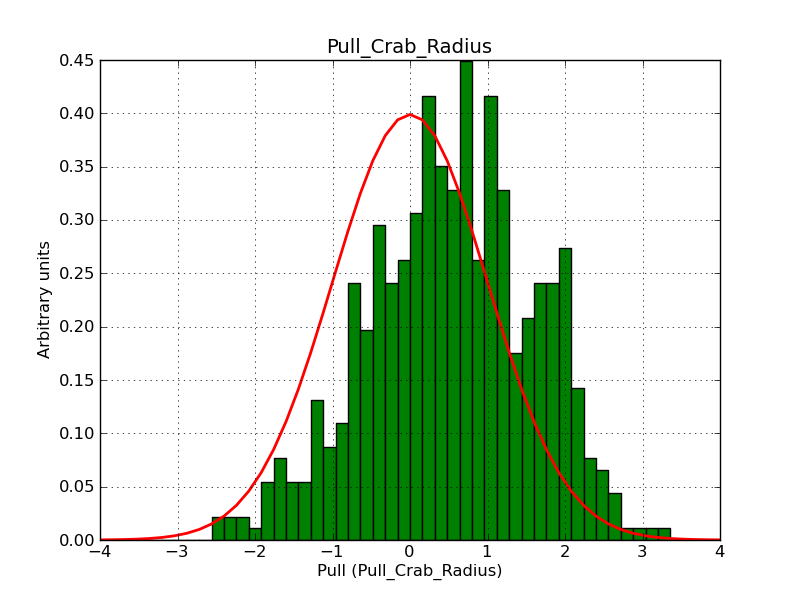
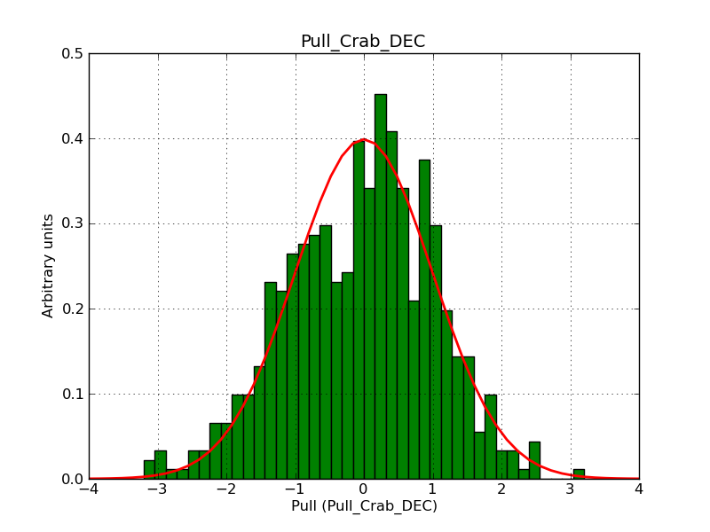
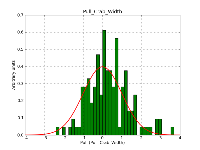
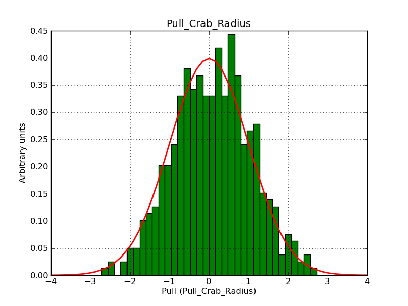
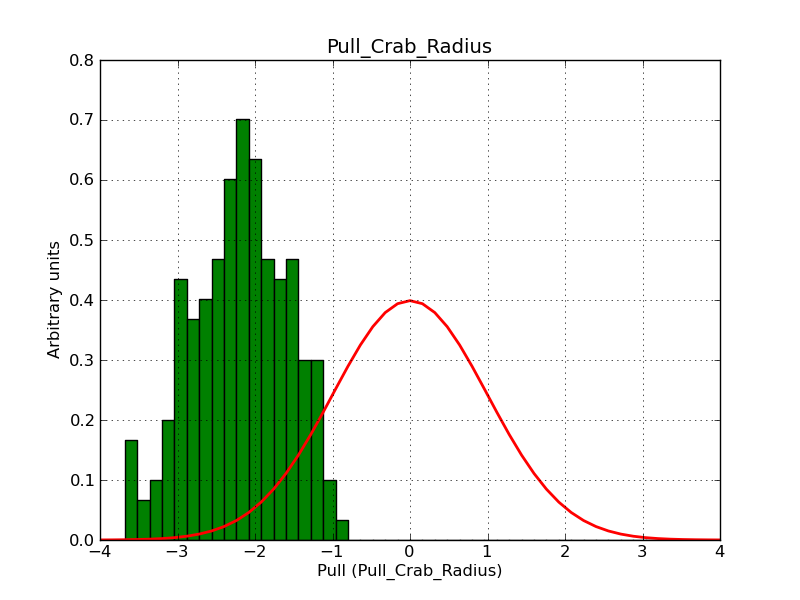
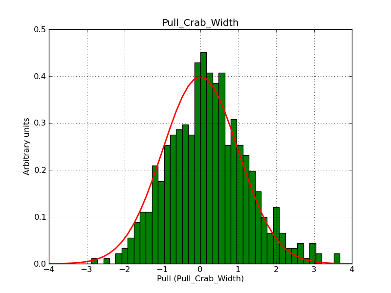
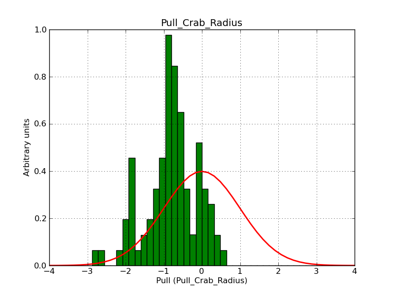
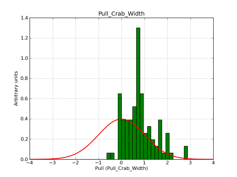
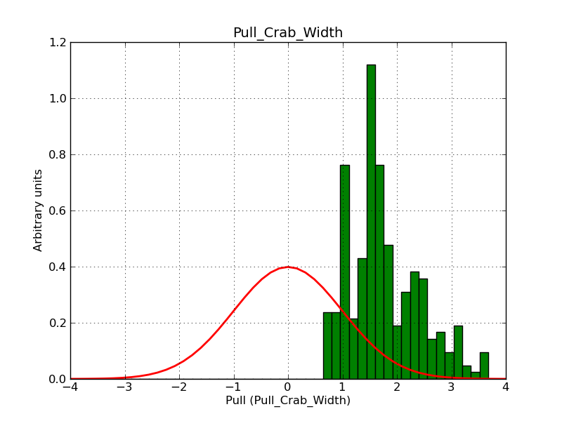
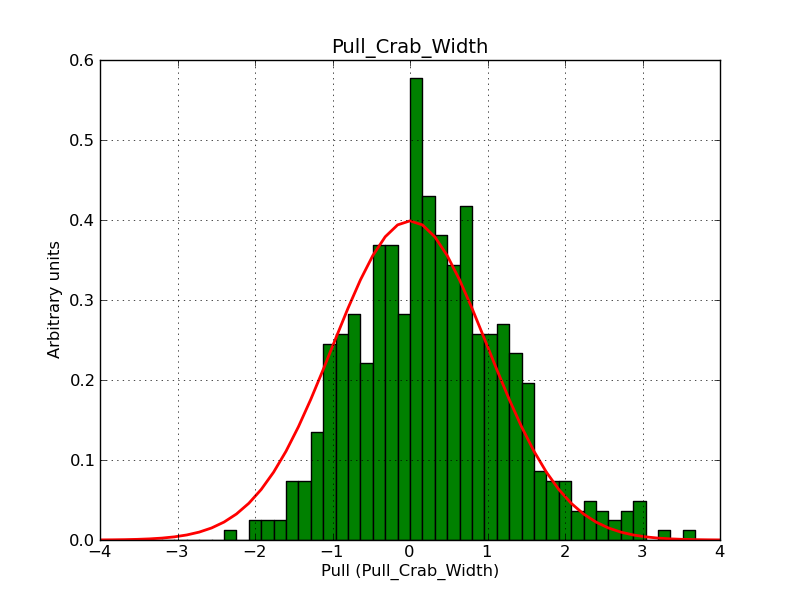
A pull distribution test on the shell model Radius and Width parameters indicates a bias:
 |
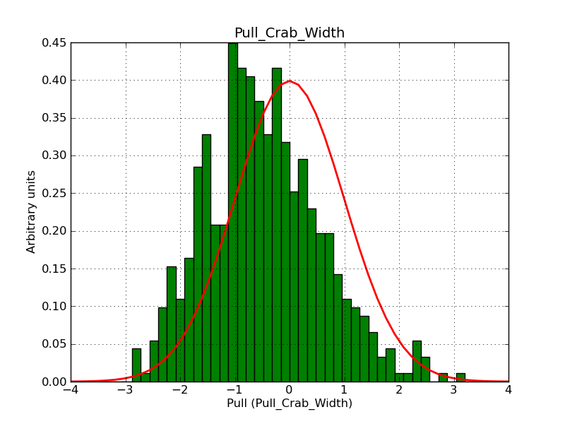 |
This should be fixed before the 1.0.0 release.
Recurrence
No recurrence.
History
#1
 Updated by Knödlseder Jürgen over 9 years ago
- Description updated (diff)
#2
 Updated by Knödlseder Jürgen over 9 years ago
Nothing special found so far. I’m wondering whether this is related to an insufficient accuracy in the log-likelihood fit (the absolute precision requirement is set to 0.005).
#3
 Updated by Knödlseder Jürgen over 9 years ago
- Status changed from New to In Progress
- Assigned To set to Knödlseder Jürgen
- % Done changed from 0 to 10
#4
 Updated by Knödlseder Jürgen over 9 years ago
- % Done changed from 10 to 20
Knödlseder Jürgen wrote:
Nothing special found so far. I’m wondering whether this is related to an insufficient accuracy in the log-likelihood fit (the absolute precision requirement is set to 0.005).
Setting the precision requirement to 1e-4 did not change the behavior.
So far I tried the following:- set iter_phi = 7 (instead of 6) in GCTAResponseIrf::nroi_radial
- set iter_rho = 7 and 8 (instead of 6) in GCTAResponseIrf::nroi_radial
- put the shell centre on the ROI centre
- put the shell 1 degree offset from the ROI centre
None of these modifications remove the bias (i.e. the bias seems to be insensitive to these changes).
Note that the shell radius was 0.3° and the shell width was 0.1° for these examples. Changing the shell radius to 1° and the shell width to 0.5° removed the bias, hence the bias seems to be related to the size of the shell.
#5
 Updated by Knödlseder Jürgen over 9 years ago
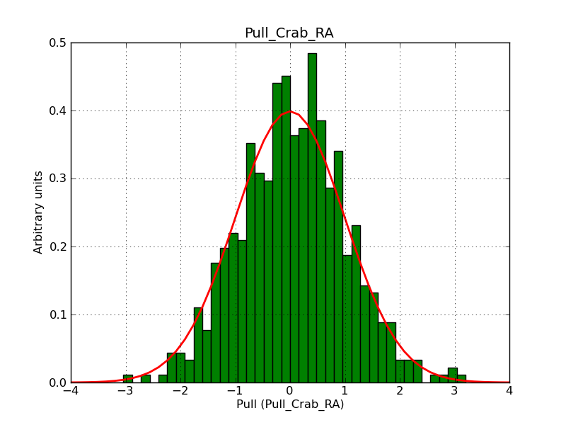
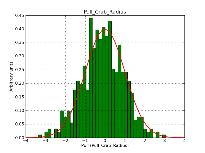
- File stacked-shell-DEC.png added
- File stacked-shell-RA.png added
- File stacked-shell-radius.png added
- File stacked-shell-width.png added
 |
 |
 |
 |
#6
 Updated by Knödlseder Jürgen over 9 years ago
- File Npred-integration.png added
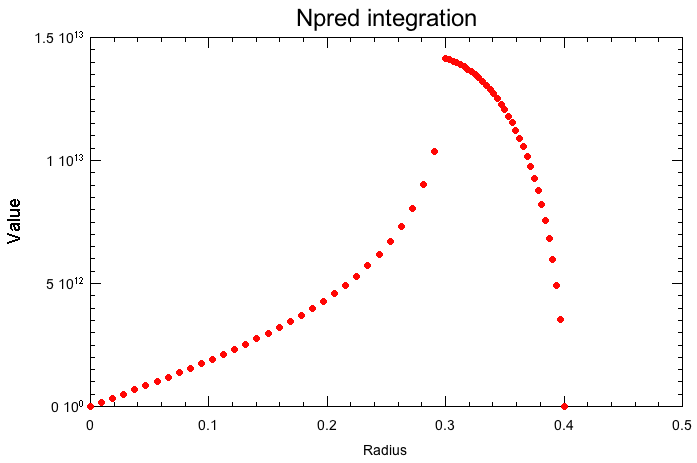
Attached a plot of the Npred integration evaluation that is done for the initial model values. Everything looks reasonable.
 |
#7
 Updated by Knödlseder Jürgen over 9 years ago
It seems that the problem is not related to the Npred computation but to the Irf computation. The precision in GCTAResponseIrf::irf_radial is set to 5 iterations in rho and in phi, and increasing the precision to 6 or 7 leads to better results. The ctlike run however has quite a number of stalls, indicating convergence problems.
Probably the reasoning behind is that for small shell widths (e.g. 0.05°) the angular size is comparable (or smaller) to the PSF size, hence the model varies substantially over the integration region (which is set by the PSF size).
#8
 Updated by Knödlseder Jürgen over 9 years ago
I now have set the number of iterations in rho and phi to 6. While this leads to convergence problems in ctlike, it gives the correct fitting results.
I did the same for the elliptical and diffuse IRF computations (hope this fixes also #1248).
#9
 Updated by Knödlseder Jürgen over 9 years ago
- File irf6-6_RA.png added
- File irf6-6_DEC.png added
- File irf6-6_Radius.png added
- File irf6-6_Width.png added
- File irf6-6_Prefactor.png added
- File irf6-6_Index.png added
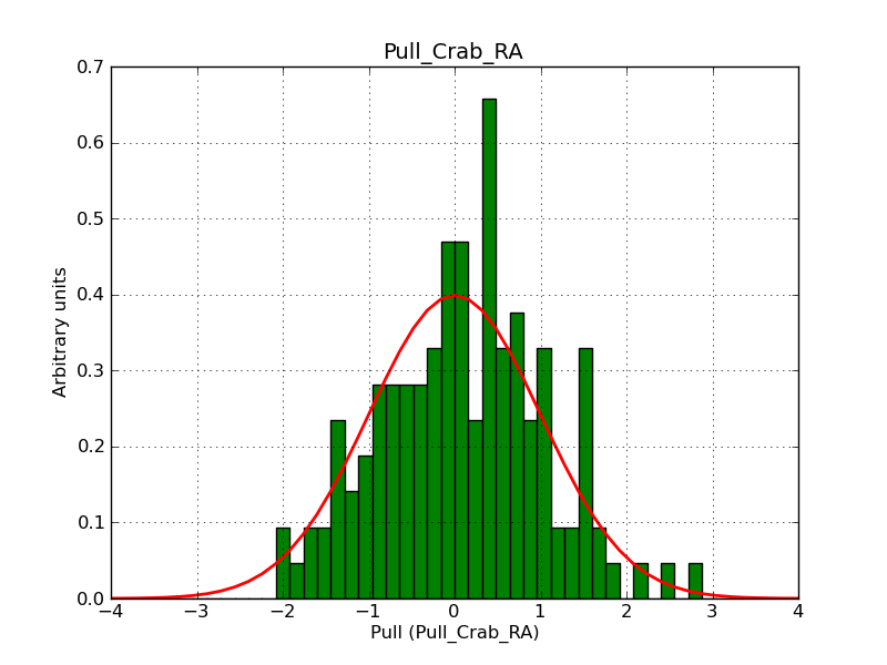
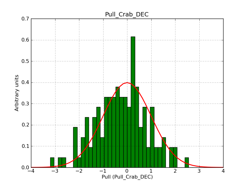
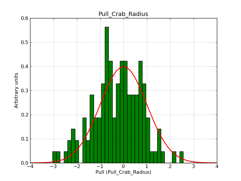
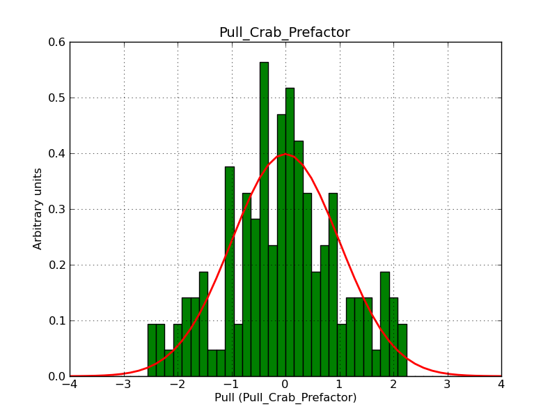
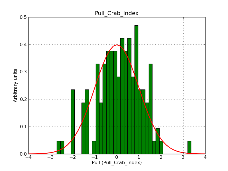
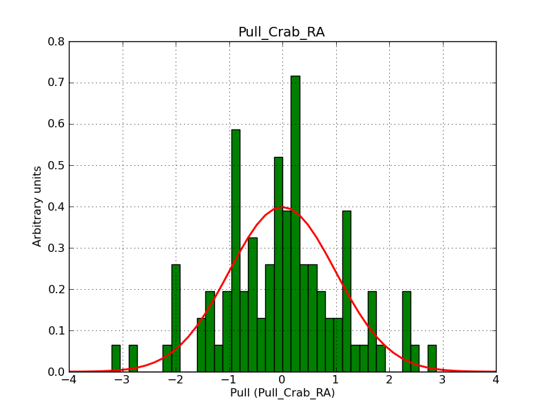
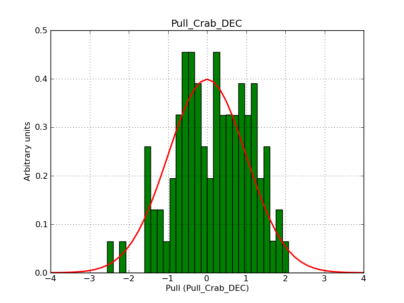
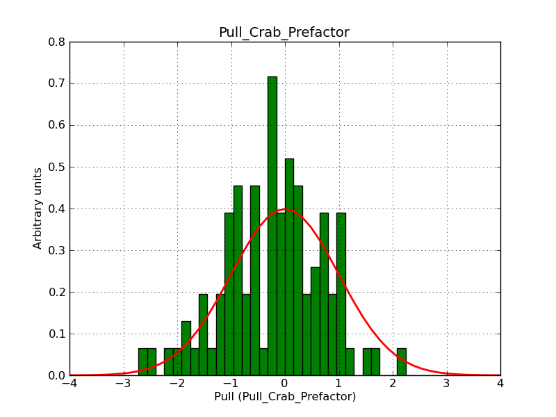
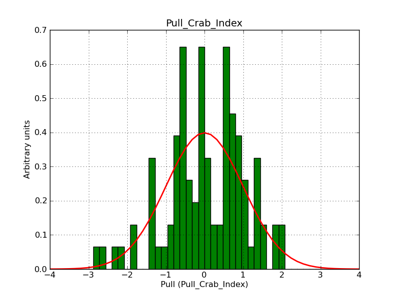
The following histograms show the pull distributions for a shell of radius 0.3° and width of 0.1° (top) and of width 0.05° (bottom). There is still a bias in radius and width for the narrow shell, but note that 0.05° is close to the angular resolution of CTA. There is also a small bias observed in the stacked analysis.
 |
 |
 |
 |
 |
 |
 |
 |
 |
 |
 |
 |
#10
 Updated by Knödlseder Jürgen over 9 years ago
- File w0.05_irf6-6_RA.png added
- File w0.05_irf6-6_DEC.png added
- File w0.05_irf6-6_Radius.png added
- File w0.05_irf6-6_Width.png added
- File w0.05_irf6-6_Prefactor.png added
- File w0.05_irf6-6_Index.png added
- % Done changed from 20 to 50
#11
 Updated by Knödlseder Jürgen over 9 years ago
Knödlseder Jürgen wrote:
I now have set the number of iterations in rho and phi to 6. While this leads to convergence problems in
ctlike, it gives the correct fitting results.I did the same for the elliptical and diffuse IRF computations (hope this fixes also #1248).
I reset the number of iterations to 5 for the diffuse IRF computations as this does not seem to fix the issue #1248. Still have to work on #1248, but this should be done independently.
#12
 Updated by Knödlseder Jürgen over 9 years ago
- File disk01.png added
- File disk02.png added
- File disk03.png added
- File disk04.png added
- File disk05.png added
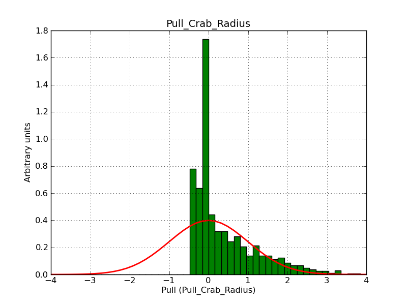
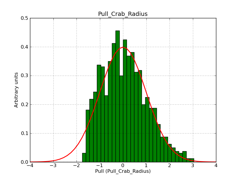
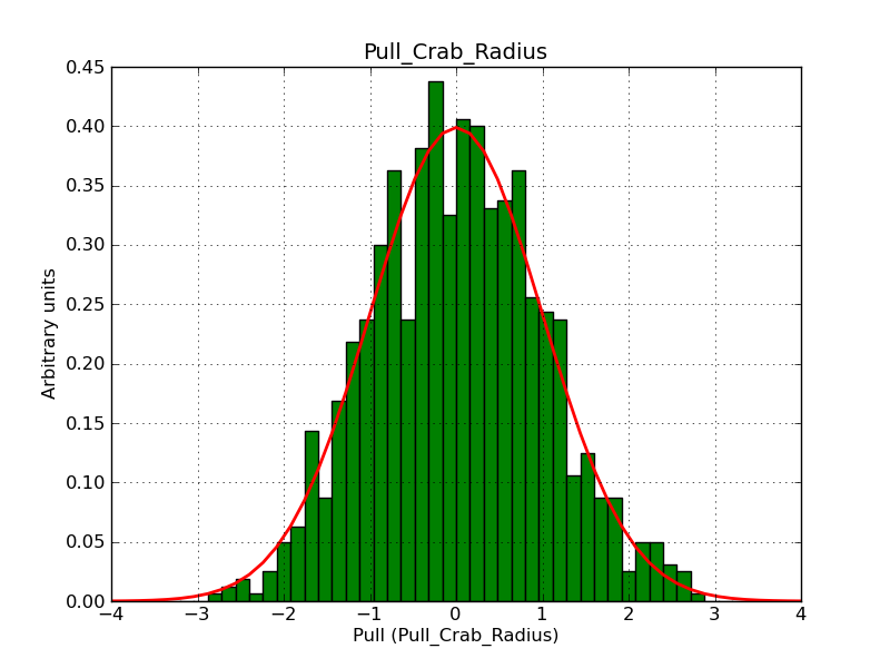
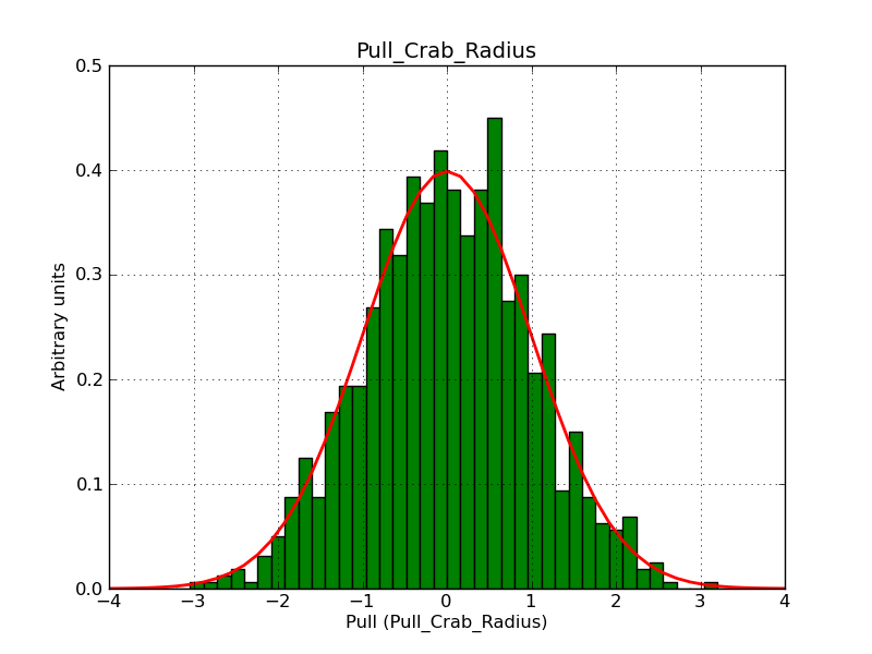
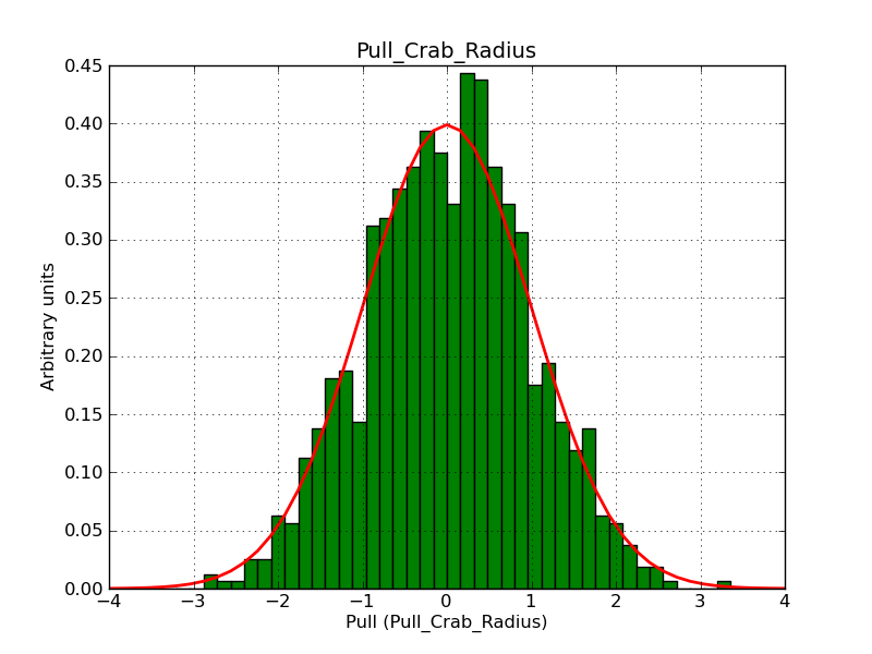
To check the new number of iterations for radial models I generated pull distributions for the disk model with radius 0.01°, 0.02°, 0.03°, 0.04° and 0.05°. This covers the transition between a disk radius that is smaller than the angular resolution to a disk radius that is larger than the angular resolution. Below the respective pull distributions. While the pull distributions for 0.01° and 0.02° are cut at the negative side, the pull distributions from 0.03° on look unbiased.
 |
 |
 |
 |
 |
#13
 Updated by Knödlseder Jürgen over 9 years ago
- File gauss5_05.png added
- File disk5_01.png added
- File disk5_02.png added
- File disk5_03.png added
- File disk5_04.png added
- File disk5_05.png added
- File gauss5_01.png added
- File gauss5_02.png added
- File gauss5_03.png added
- File gauss5_04.png added
- % Done changed from 50 to 60
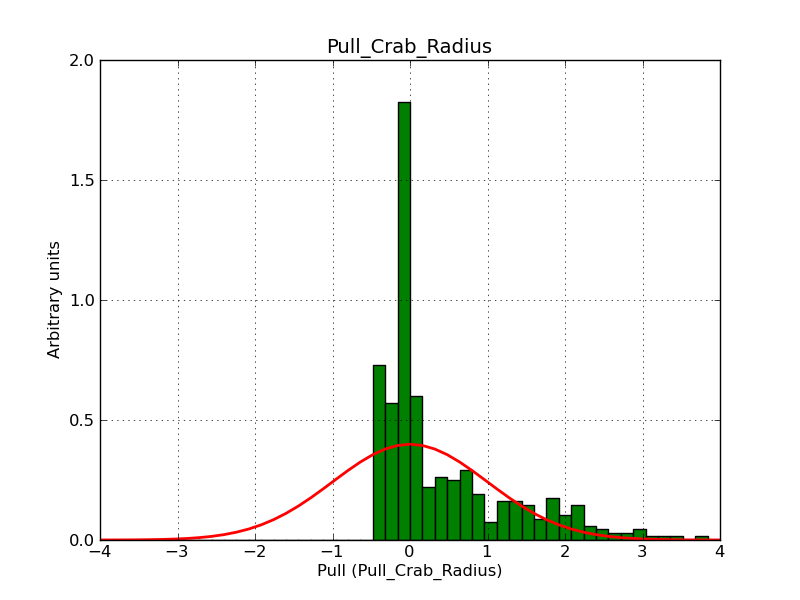
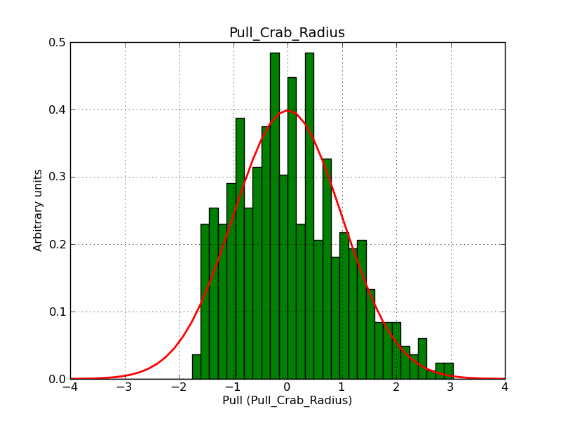
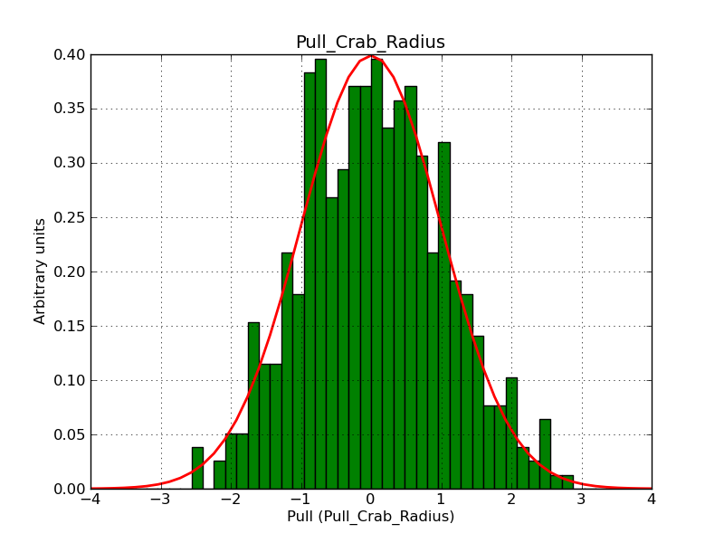
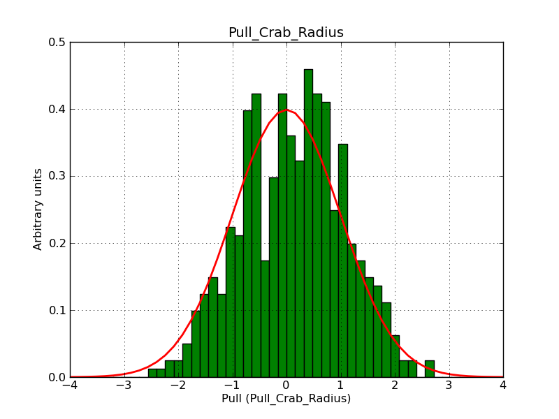
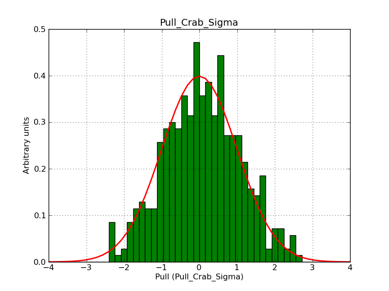
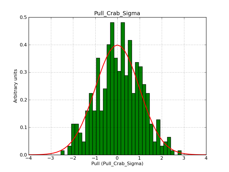
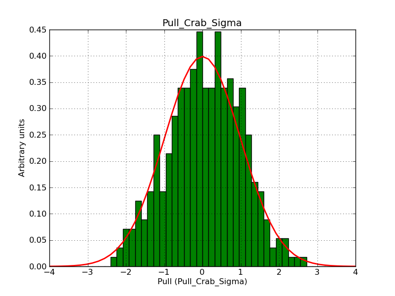
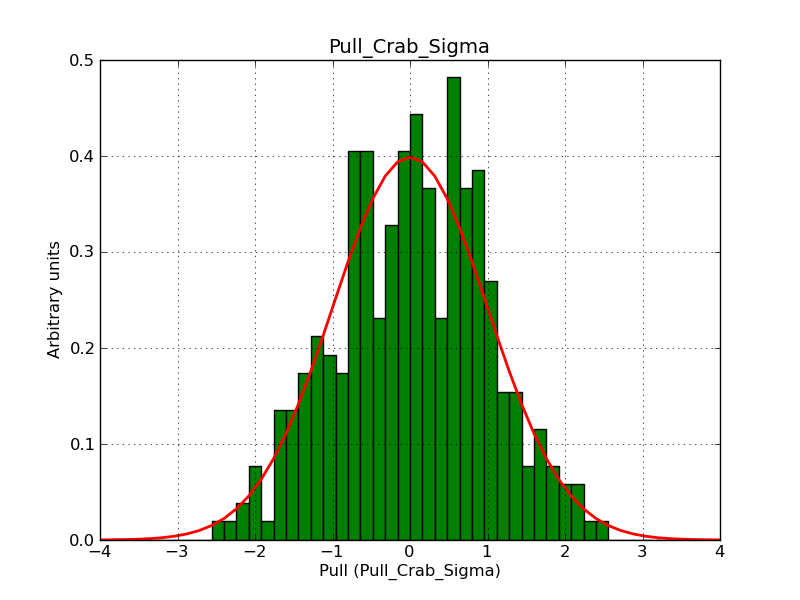
I checked whether the disk and gaussian model also give reasonable results at the limit of the CTA angular resolution with and iteration depth of 5 in rho and phi. The following pull distributions demonstrate that this is the case (top row: disk model, bottom row: gaussian model; sizes are from left to right: 0.01°, 0.02°, 0.03°, 0.04° and 0.05°. Therefore, for non-shell radial models I leave the IRF iteration depth at 5 (leading to faster computation w/r to 6).
 |
 |
 |
 |
 |
 |
 |
 |
 |
 |
#14
 Updated by Knödlseder Jürgen over 9 years ago
Below are pull histograms for an IRF iteration depth of 6 and shell widths of 0.01°, 0.02°, 0.03° and 0.05°.
| 0.01° |  |
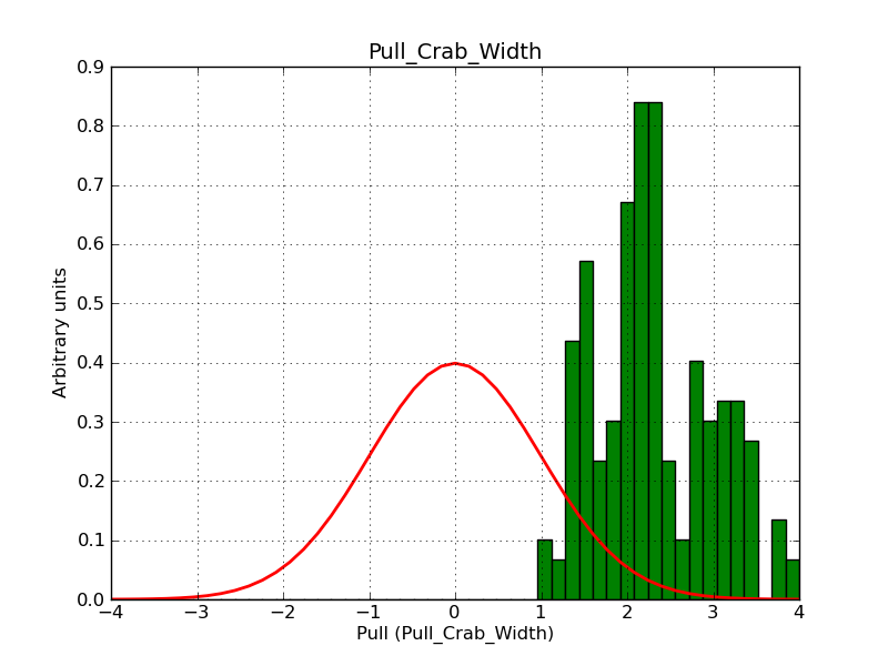 |
| 0.02° | 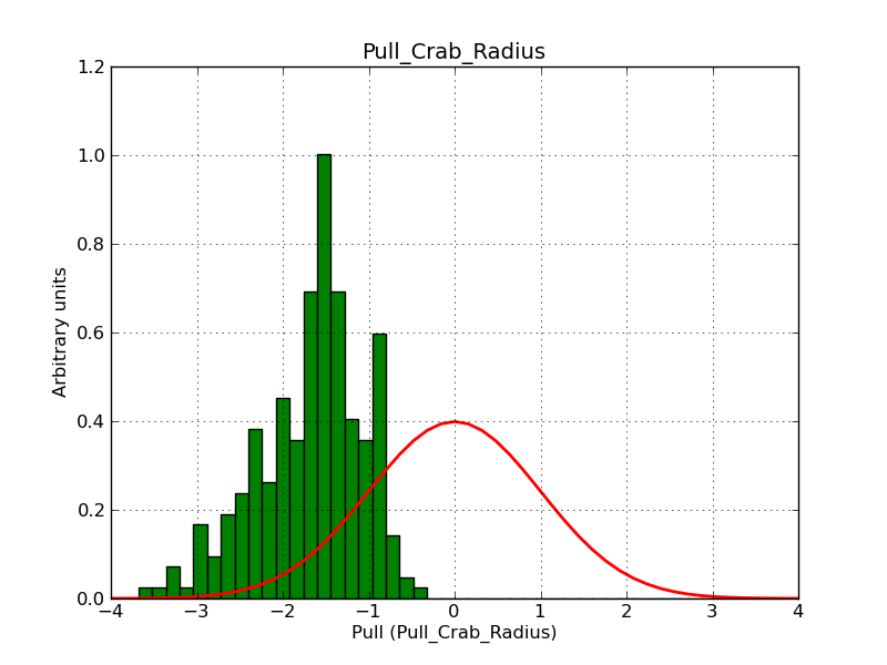 |
 |
| 0.03° |  |
 |
| 0.05° |  |
 |
| 0.10° | 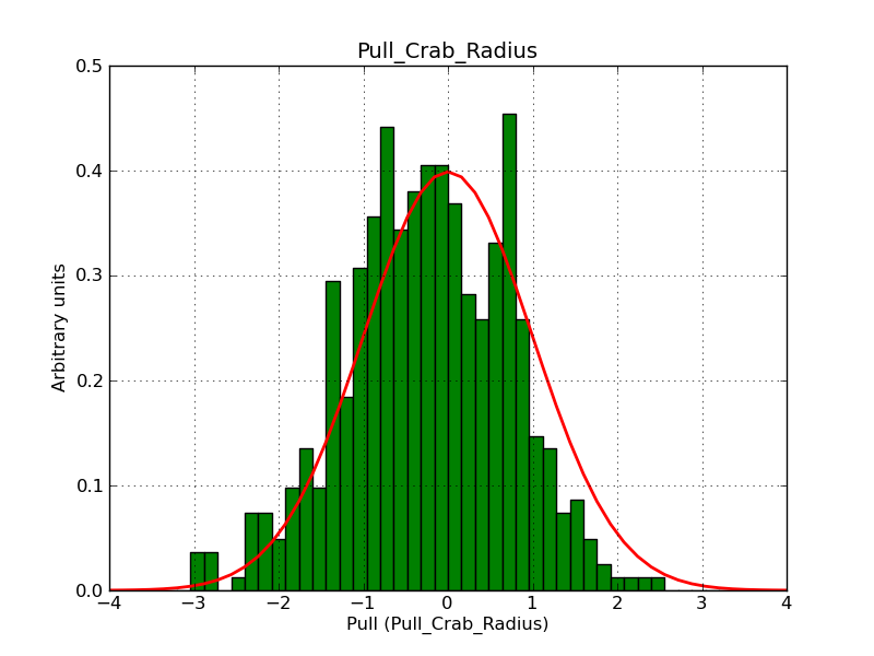 |
 |
#15
 Updated by Knödlseder Jürgen over 9 years ago
- File w0.01_irf6-6_Radius.png added
- File w0.01_irf6-6_Width.png added
- File w0.02_irf6-6_Radius.png added
- File w0.02_irf6-6_Width.png added
#16
 Updated by Knödlseder Jürgen over 9 years ago
- File w0.10_irf6-6_Radius.png added
- File w0.10_irf6-6_Width.png added
#17
 Updated by Knödlseder Jürgen over 9 years ago
- File crab_shell_0.3_0.01_1-2TeV.png added
- File crab_shell_0.28_0.046_1-2TeV.png added
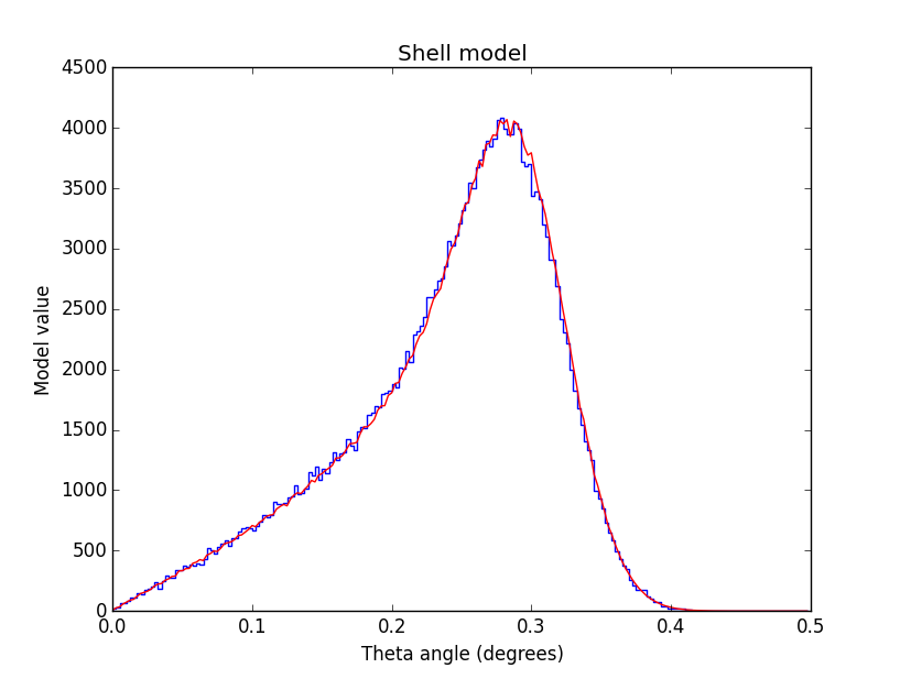
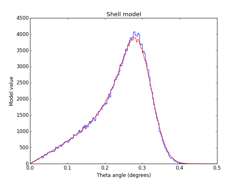
Below are radial profiles of shell models in the 1-2 TeV range. On the left the shell parameters were r=0.3° and w=0.01°, on the right the shell parameters were r=0.28° and w=0.046°. The profiles look very similar. Note that the fit convergence is not very good for shells with narrow width (see excerpt below). Possibly the fit has simply problems finding the minimum.
 |
 |
2015-10-14T12:25:36:  >Iteration   0: -logL=108069.088, Lambda=1.0e-03
2015-10-14T12:25:36:    Parameter "Radius" drives optimization step (step=0.581703)
2015-10-14T12:27:51:   Iteration   1: -logL=108069.088, Lambda=1.0e-03, delta=-1214.245, max(|grad|)=3560.961511 [Radius:2] (stalled)
2015-10-14T12:27:51:    Parameter "Radius" does not drive optimization step anymore.
2015-10-14T12:30:08:   Iteration   2: -logL=108069.088, Lambda=1.0e-02, delta=-1122.984, max(|grad|)=3703.983556 [Radius:2] (stalled)
2015-10-14T12:32:25:   Iteration   3: -logL=108069.088, Lambda=1.0e-01, delta=-39.914, max(|grad|)=3282.352875 [Radius:2] (stalled)
2015-10-14T12:34:38:  >Iteration   4: -logL=108058.279, Lambda=1.0e+00, delta=10.809, max(|grad|)=1385.439966 [Radius:2]
2015-10-14T12:36:51:  >Iteration   5: -logL=108052.492, Lambda=1.0e-01, delta=5.787, max(|grad|)=207.624895 [Radius:2]
2015-10-14T12:39:07:   Iteration   6: -logL=108052.528, Lambda=1.0e-02, delta=-0.036, max(|grad|)=106.863003 [Width:3] (stalled)
2015-10-14T12:41:20:  >Iteration   7: -logL=108052.302, Lambda=1.0e-01, delta=0.226, max(|grad|)=-58.405796 [Radius:2]
2015-10-14T12:43:35:  >Iteration   8: -logL=108052.225, Lambda=1.0e-02, delta=0.077, max(|grad|)=23.955635 [DEC:1]
2015-10-14T12:45:51:   Iteration   9: -logL=108052.375, Lambda=1.0e-03, delta=-0.150, max(|grad|)=64.127946 [Width:3] (stalled)
2015-10-14T12:48:04:  >Iteration  10: -logL=108052.255, Lambda=1.0e-02, delta=0.120, max(|grad|)=37.344665 [DEC:1]
2015-10-14T12:50:18:   Iteration  11: -logL=108052.533, Lambda=1.0e-03, delta=-0.277, max(|grad|)=90.447630 [Width:3] (stalled)
2015-10-14T12:52:35:  >Iteration  12: -logL=108052.284, Lambda=1.0e-02, delta=0.249, max(|grad|)=46.836933 [DEC:1]
2015-10-14T12:54:46:   Iteration  13: -logL=108052.284, Lambda=1.0e-03, delta=-0.396, max(|grad|)=111.588199 [Width:3] (stalled)
2015-10-14T12:57:05:   Iteration  14: -logL=108052.284, Lambda=1.0e-02, delta=-0.011, max(|grad|)=59.407164 [Width:3] (stalled)
2015-10-14T12:59:20:  >Iteration  15: -logL=108052.206, Lambda=1.0e-01, delta=0.078, max(|grad|)=34.066836 [Radius:2]
2015-10-14T13:01:34:  >Iteration  16: -logL=108052.199, Lambda=1.0e-02, delta=0.006, max(|grad|)=23.223715 [Width:3]
2015-10-14T13:03:47:   Iteration  17: -logL=108052.199, Lambda=1.0e-03, delta=-0.042, max(|grad|)=-27.212419 [Width:3] (stalled)
2015-10-14T13:06:00:  >Iteration  18: -logL=108052.190, Lambda=1.0e-02, delta=0.009, max(|grad|)=-15.701380 [Width:3]
2015-10-14T13:08:14:   Iteration  19: -logL=108052.190, Lambda=1.0e-03, delta=-0.045, max(|grad|)=32.002318 [Width:3] (stalled)
2015-10-14T13:10:28:  >Iteration  20: -logL=108052.189, Lambda=1.0e-02, delta=0.001, max(|grad|)=17.863560 [Width:3]
#18
 Updated by Knödlseder Jürgen over 9 years ago
Maybe the problem is that for a width that is smaller than the angular resolution the width parameter becomes basically unconstrained and the strong correlation with the radius does not allow to find a good solution.
#19
 Updated by Knödlseder Jürgen over 9 years ago
- Status changed from In Progress to Closed
- % Done changed from 60 to 100
Below a table of the resulting radius and width parameters as a function of the IRF integration depth. The simulated shell radius was 0.3°, the simulated shell width was 0.01°.
| Integration depth | Radius | Width | Iterations | -logL |
| 5 | 0.298800 | 0.01 | 9 | 108008.884 |
| 6 | 0.279862 | 0.0455535 | 20 | 108052.189 |
| 7 | 0.274953 | 0.053962 | 18 | 108054.513 |
| 8 | 0.274230 | 0.055146 | 20 | 108055.228 |
I thus changed the integration depth in the code to 6. Higher would even be better but the computing time becomes prohibitive for values above 6.
This issue is not fully fixed, but the performance should be acceptable for the first release. I will add a warning in the ctools documentation that the shell width becomes biased (towards larger values) when the width becomes comparable to the angular resolution.
